True Position Calculator
Enter nominal and measured coordinates to get true position, then add the feature size to apply the MMC bonus and check pass or fail.
A true position calculator measures how far a hole or pin sits from its nominal location, then compares that distance with the position tolerance to show PASS or FAIL. Enter the nominal and measured X and Y values, along with the position tolerance from your drawing, and the tool returns the true position as a diameter. It supports RFS and MMC conditions, including bonus tolerance, and works in inches or millimetres.
The tool runs in your browser. It is free, needs no sign-up, and works on a phone, so you can check a feature at the machine or on the inspection bench.
How to use the True Position Calculator
- Choose the unit: inch or mm.
- Enter the nominal X and Y. These are the basic dimensions from your drawing.
- Enter the measured X and Y from your inspection.
- Enter the position tolerance as the diameter in the feature control frame, for example ⌀0.005.
- Select the material condition: RFS (no bonus), MMC for a hole, or MMC for a pin or boss.
- If you selected an MMC option, enter the MMC size and the actual measured size. The bonus tolerance is calculated from these two values.
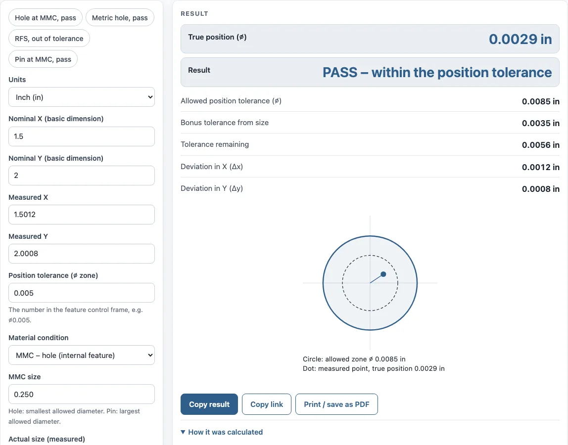
- Read the results: true position (⌀), PASS or FAIL, allowed position tolerance including bonus, bonus tolerance, tolerance remaining, Δx and Δy. The drawing shows the tolerance circle, the bonus zone and the measured point.
Results update as you type, so you can change any input and see the outcome immediately.
For plus/minus coordinate tolerances, open More options and enter ±X and ±Y. The tool gives the equivalent diametral position tolerance. When you are finished, Copy result copies the result lines with a link, and Copy link copies the page address. That address stores every input, so opening it later restores the same calculation.
Copy result and Print / save as PDF include the PASS or FAIL line, so the printout can go with an inspection report.
What is the formula for true position?
True position is 2 × √(Δx² + Δy²), where Δx is measured X minus nominal X, and Δy is measured Y minus nominal Y. The result is a diameter, so you can compare it directly with the ⌀ value in the feature control frame.
The square root gives the straight-line distance from the nominal location to the measured point. The factor of 2 is needed because a position tolerance zone is a diameter, not a radius. ASME Y14.5 defines it as a cylindrical zone centred on the basic location, so the distance is doubled to match.
To work it by hand:
- Subtract the nominal from the measured value for each axis to get Δx and Δy.
- Square each one and add the two squares.
- Take the square root of the sum.
- Multiply the result by 2.
For Δx 0.0040 in and Δy 0.0030 in, the squares are 0.000016 and 0.000009. Their sum is 0.000025, the square root is 0.0050, and doubling it gives a true position of 0.0100 in.
How do you calculate positional tolerance?
Start with the position tolerance from the feature control frame, then compare the true position with the allowed value. At RFS, the allowed value is the tolerance itself, whatever the feature size. The feature passes when the true position is less than or equal to the allowed value.
Tolerance remaining is the allowed value minus the true position. It shows how much room is left before the feature fails.
For Δx 0.0012 in, Δy 0.0008 in and a ⌀0.005 in tolerance at RFS, the true position is 0.0029 in. The allowed value is 0.0050 in, so the feature passes with 0.0021 in remaining.
For Δx 0.0040 in, Δy 0.0030 in and the same tolerance at RFS, the true position is 0.0100 in. That is twice the allowed value, so the feature fails.
Use one unit throughout. The coordinates and the tolerance must both be in inches or both in millimetres, so choose the unit before you enter values. Lengths show 4 decimals in inches and 3 in mm. If a result is close to the limit, check the Δx and Δy values before you decide.
Sources
- Geometric dimensioning and tolerancing (Wikipedia) — ASME Y14.5 position with a diametral zone, TP = 2 √(Δx² + Δy²), MMC bonus tolerance
Worked examples
| Input | Result |
|---|---|
| Δx 0.0012 in, Δy 0.0008 in, tolerance ⌀ 0.005 in | TP 0.0029 in against 0.0085 in allowed: PASS – within the position tolerance |
| Δx 0.060 mm, Δy -0.030 mm, tolerance ⌀ 0.15 mm | TP 0.134 mm against 0.200 mm allowed: PASS – within the position tolerance |
| Δx 0.0040 in, Δy 0.0030 in, tolerance ⌀ 0.005 in | TP 0.0100 in against 0.0050 in allowed: FAIL – outside the position tolerance |
| Δx 0.100 mm, Δy 0.050 mm, tolerance ⌀ 0.2 mm | TP 0.224 mm against 0.250 mm allowed: PASS – within the position tolerance |
| Δx 0.0000 in, Δy 0.0000 in, tolerance ⌀ 0.01 in | TP 0.0000 in against 0.0100 in allowed: PASS – within the position tolerance |
Calculated by the tool above with these values.
Frequently asked questions
How does MMC bonus tolerance work?
At MMC, extra tolerance is added as the feature moves away from its MMC size. For a hole, bonus equals actual size minus MMC size, which is the smallest allowed hole. For a pin or boss, bonus equals MMC size minus actual size, which is the largest allowed pin.
The allowed position tolerance is the drawing tolerance plus the bonus. Bonus is never negative. If the feature is outside its size limit, the tool shows a warning and gives no bonus.
How do you convert plus/minus tolerance to true position?
Enter the ±X and ±Y coordinate tolerances in More options, and the tool calculates the equivalent diametral position tolerance as 2√(tx² + ty²). For example, ±0.005 in on both axes equals ⌀0.0141 in.
Use the converted value when a drawing or specification gives coordinate limits instead of a position callout.
What is the difference between RFS and MMC?
RFS (regardless of feature size) gives no bonus. The allowed position tolerance stays the same whatever the actual size of the feature.
MMC (maximum material condition) allows bonus tolerance as the feature moves away from its MMC size. Select the material condition that matches the feature control frame on your drawing, because the allowed value depends on it.
Can I print the inspection result?
Yes. Print / save as PDF prints the inputs, results, calculation steps and the date. You can save the output as a PDF for an inspection record or attach it to a setup sheet.
What does the warning about three times the tolerance mean?
The tool shows a warning when the measured point is more than three times the allowed tolerance away from the nominal location. This usually means the datum setup or the nominal values are wrong.
Check the nominal X and Y values and your datum setup before you accept a FAIL result.
Related tools
- Bolt circle calculator: Use it to find hole coordinates on a bolt circle, then check those coordinates with the true position calculator.
- Sine bar calculator: Use it to set an angle on a sine bar when you need to locate or inspect an angled feature.
- Surface finish calculator: Use it to convert and check surface roughness values on the same drawing.
- Drill and tap chart: Use it to find the correct drill size before a hole is machined to its position tolerance.
- Decimal to fraction inches: Use it to convert decimal inch dimensions to fractions when a drawing or gauge uses them.
- Tenths to inches calculator: use it to convert tolerances given in tenths or mm to decimal inches.
- GD&T symbols chart: use it to look up what each geometric tolerance symbol controls.
- All machining calculators: Use it to browse every calculator on the site.