GD&T Symbols Chart
Pick a geometric tolerance symbol to see what it controls, whether it needs a datum, its tolerance zone and a typical use.
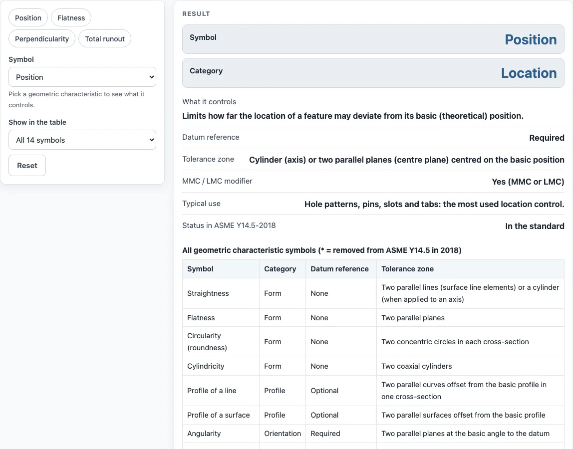
This GD&T symbols chart lists the 14 geometric characteristic symbols of ASME Y14.5 and tells you what each one controls. Choose a symbol and you get its category (form, profile, orientation, location or runout), whether a datum reference is needed, the shape of its tolerance zone, whether the MMC or LMC modifier can be used, and a typical use on a drawing. The table below the result lists all symbols at once, and you can filter it by category.
It is meant for machinists, inspectors and designers who meet a feature control frame on a print and need to know what the first box means before they set up or measure the part. Everything runs in your browser, with no sign-up.
How to use the GD&T symbols chart
- Open the Symbol list and choose the geometric characteristic you want to read, such as Position or Flatness. The chip buttons above the form jump to common ones.
- Read the big result: the symbol name and its category.
- Below it, read what the tolerance controls, whether a datum reference is required, the tolerance zone and the MMC / LMC note.
- Check “Status in ASME Y14.5-2018”. Concentricity and symmetry show a warning because the 2018 edition removed them.
- Use “Show in the table” to list only one category, for example only the four form tolerances. The table always marks the two removed symbols with an asterisk.
The drawing beside the result is the symbol as it appears in the first compartment of a feature control frame. The page address keeps your choice, so you can share a link to a symbol or reopen it later on another device. Print / save as PDF prints the result and the table with the date. The chart works the same on a phone at the machine, so you can look a symbol up while you read the print. Nothing you select is uploaded or stored, and the link needs no account.
What is GD&T?
GD&T stands for geometric dimensioning and tolerancing. It is a drawing language, defined in ASME Y14.5 (and ISO 1101 elsewhere), that controls the form, orientation, location and runout of features instead of only their size. A feature control frame is a box on the drawing. From left to right it holds the symbol, the tolerance value (with a diameter sign when the zone is a cylinder), and the datum letters the feature is measured from.
What are the 14 GD&T symbols?
They sit in five groups. Form: straightness, flatness, circularity and cylindricity, none of which use a datum. Profile: profile of a line and profile of a surface, where a datum is optional. Orientation: angularity, perpendicularity and parallelism, which always need a datum. Location: position, concentricity and symmetry. Runout: circular runout and total runout, both measured about a datum axis.
Which GD&T symbols need a datum?
Orientation, location and runout symbols need at least one datum reference, because they describe a relationship to something else. Form symbols do not, since they only compare a feature to its own ideal shape. Profile may be used with or without a datum, depending on whether the surface is controlled by itself or related to others.
Were concentricity and symmetry removed from GD&T?
Yes, from ASME Y14.5 in the 2018 edition. Drawings that still call out the 2009 edition can use them, and ISO 1101 keeps both. Where you meet them on a newer print, the usual substitutes are position, runout or profile, which are easier to inspect.
What does the diameter sign in a feature control frame mean?
A diameter sign in front of the tolerance value means the zone is a cylinder around the axis. Without it the zone is the space between two parallel planes or lines. Position with a diameter sign is the common way to locate a round hole.
Sources
- GD&T Symbol Cheat Sheet – all 14 tolerances explained (AIMS Industrial): categories, datum use, tolerance zones, MMC / LMC applicability. Checked October 2026.
- Concentricity – elimination from the ASME Y14.5 2018 standard (GDandTbasics.com): removal of concentricity and symmetry in 2018.
- The wording of each description is ours; the standard itself (ASME Y14.5) is the authority, and this page does not reproduce it.
Worked examples
| Input | Result |
|---|---|
| Position | Location control; datum reference: Required |
| Flatness | Form control; datum reference: None |
| Perpendicularity | Orientation control; datum reference: Required |
| Total runout | Runout control; datum reference: Required (a datum axis) |
| Concentricity | Location control; datum reference: Required |
Calculated by the tool above with these values.
Frequently asked questions
Is the position symbol the same as true position?
Yes. The position symbol sets a true position tolerance: the feature’s axis or centre plane must lie inside the zone around its basic location. The true position calculator turns measured coordinates into a position value and checks it against the tolerance.
Can I use MMC with every GD&T symbol?
No. The maximum material condition modifier applies to a tolerance on a feature of size, such as a hole or pin, and mainly with position and the orientation tolerances. It is not used with flatness, circularity, cylindricity, profile or runout.
What is the difference between circular runout and total runout?
Circular runout is checked at each cross-section on its own as the part turns. Total runout covers the whole surface at once, so it also controls taper and straightness along the length. Total runout is the stricter of the two.
Do I need to know the datum letters to use the chart?
No. The chart explains what each symbol controls. The datum letters are on your drawing; the symbol only tells you whether any are required.
Does this chart replace the ASME Y14.5 standard?
No. It is a quick reference. For rules on modifiers, datum order and zone sizes, use the edition of the standard your drawing calls out in its title block.
Related tools
- True position calculator: use it to check a hole location against a position tolerance.
- Sine bar calculator: use it to set a part at an angle when you measure angularity.
- Taper angle calculator: use it to work out the angle of a tapered feature.
- Surface finish calculator: use it to convert roughness values on a drawing.
- Bolt circle calculator: use it to get hole coordinates for a position pattern.
- All machining calculators: use it to browse every calculator on the site.